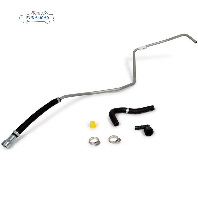
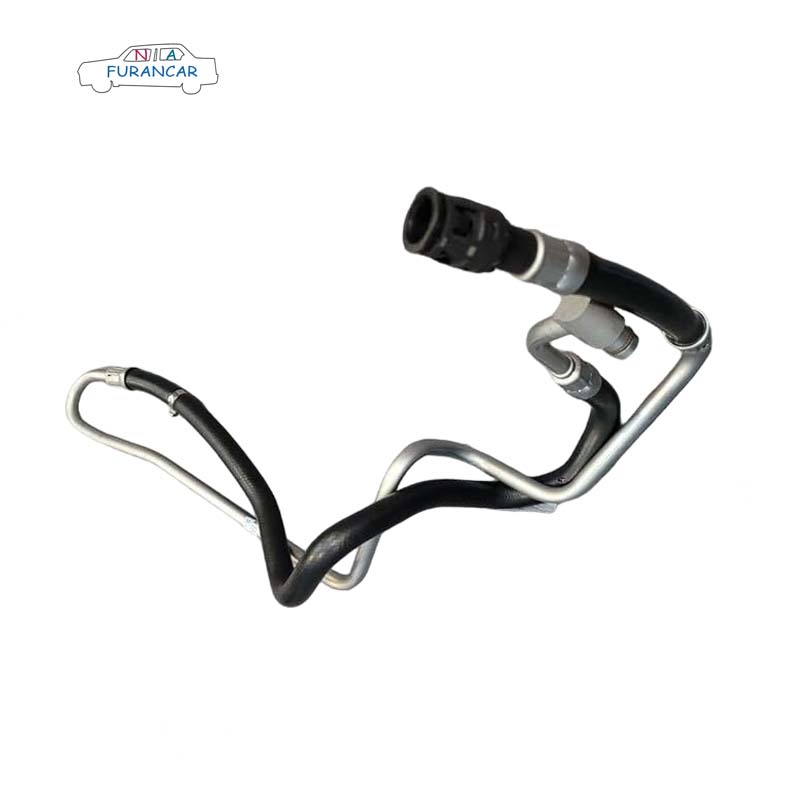
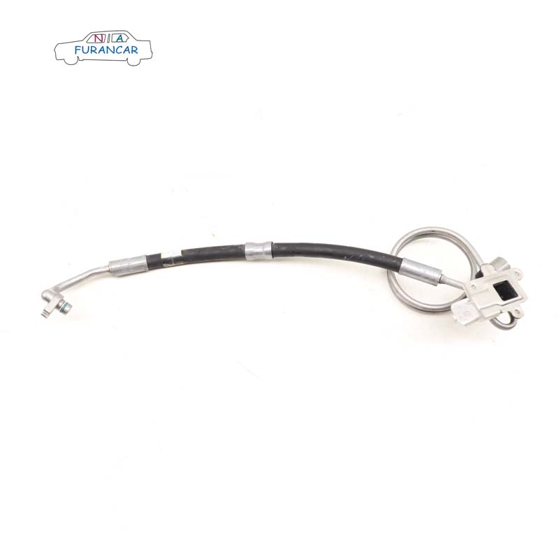
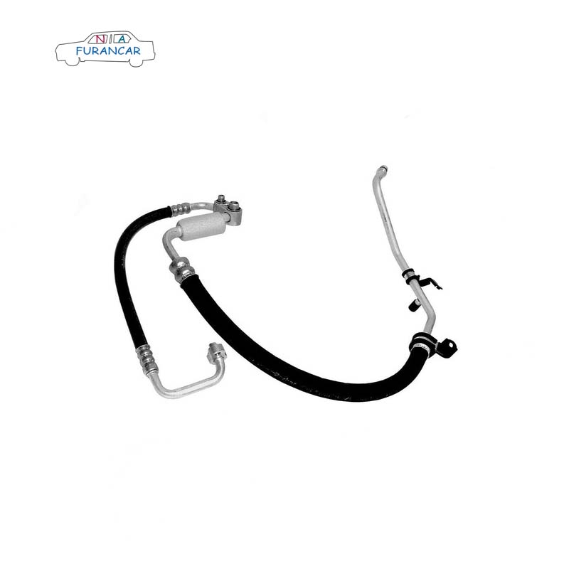
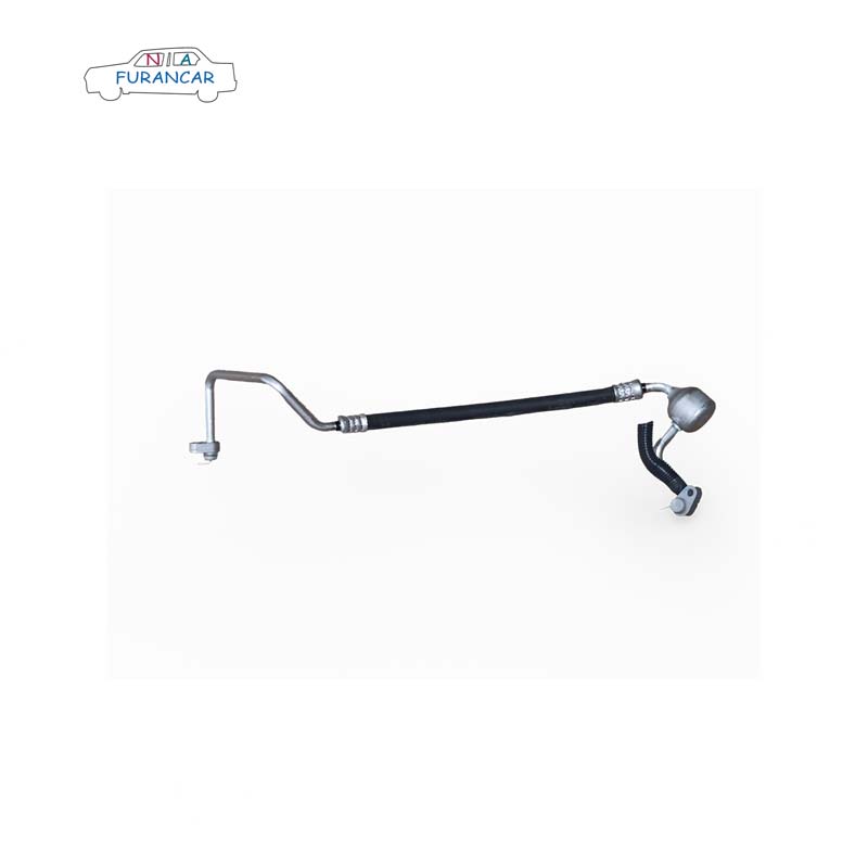
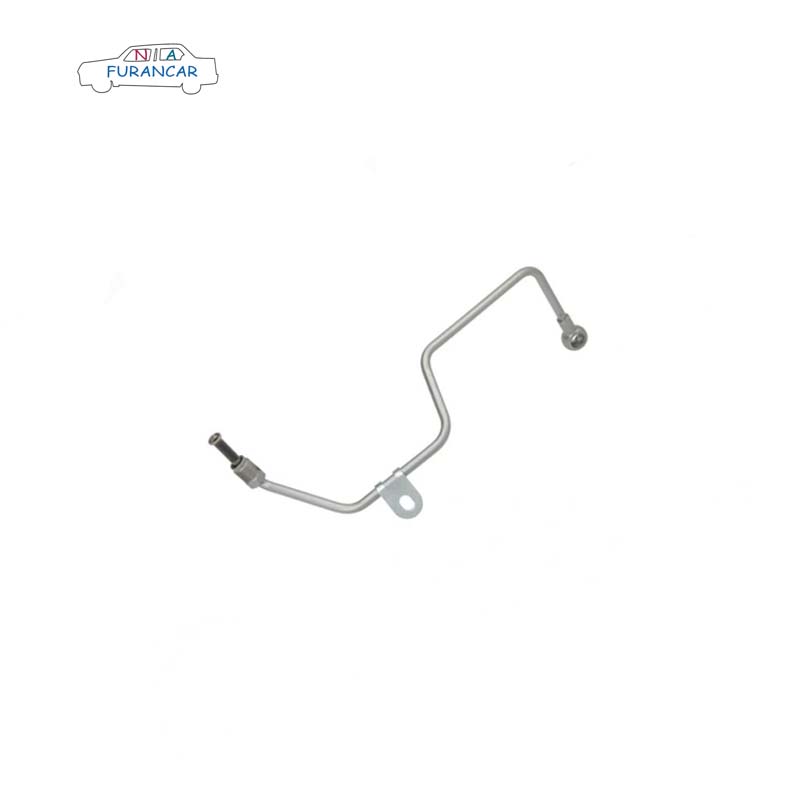
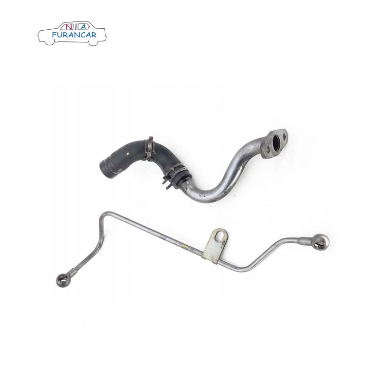
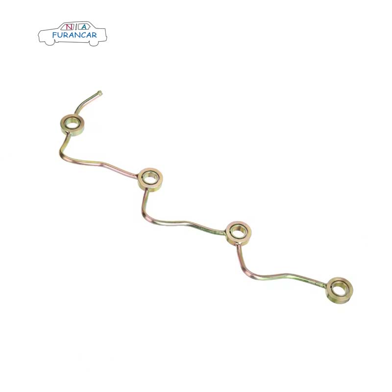
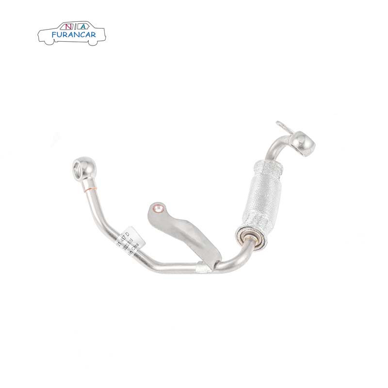
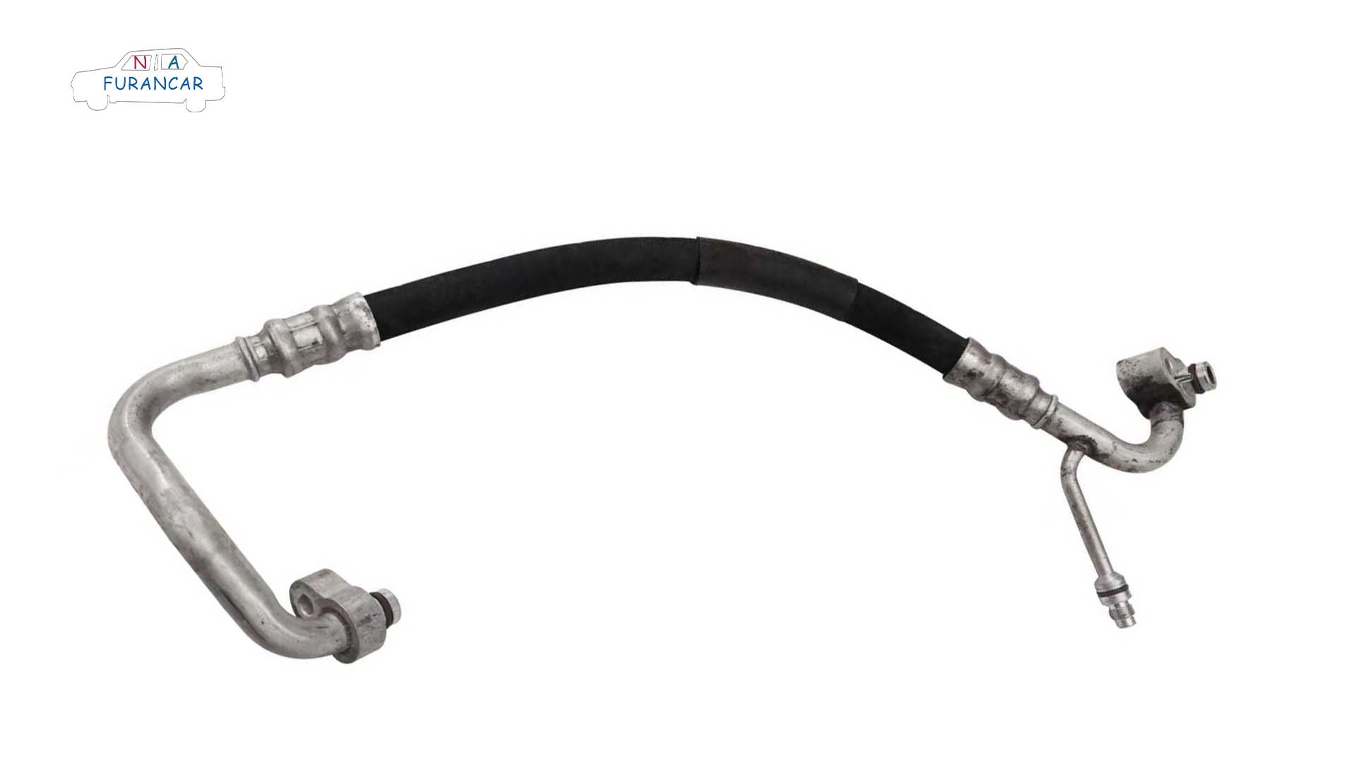
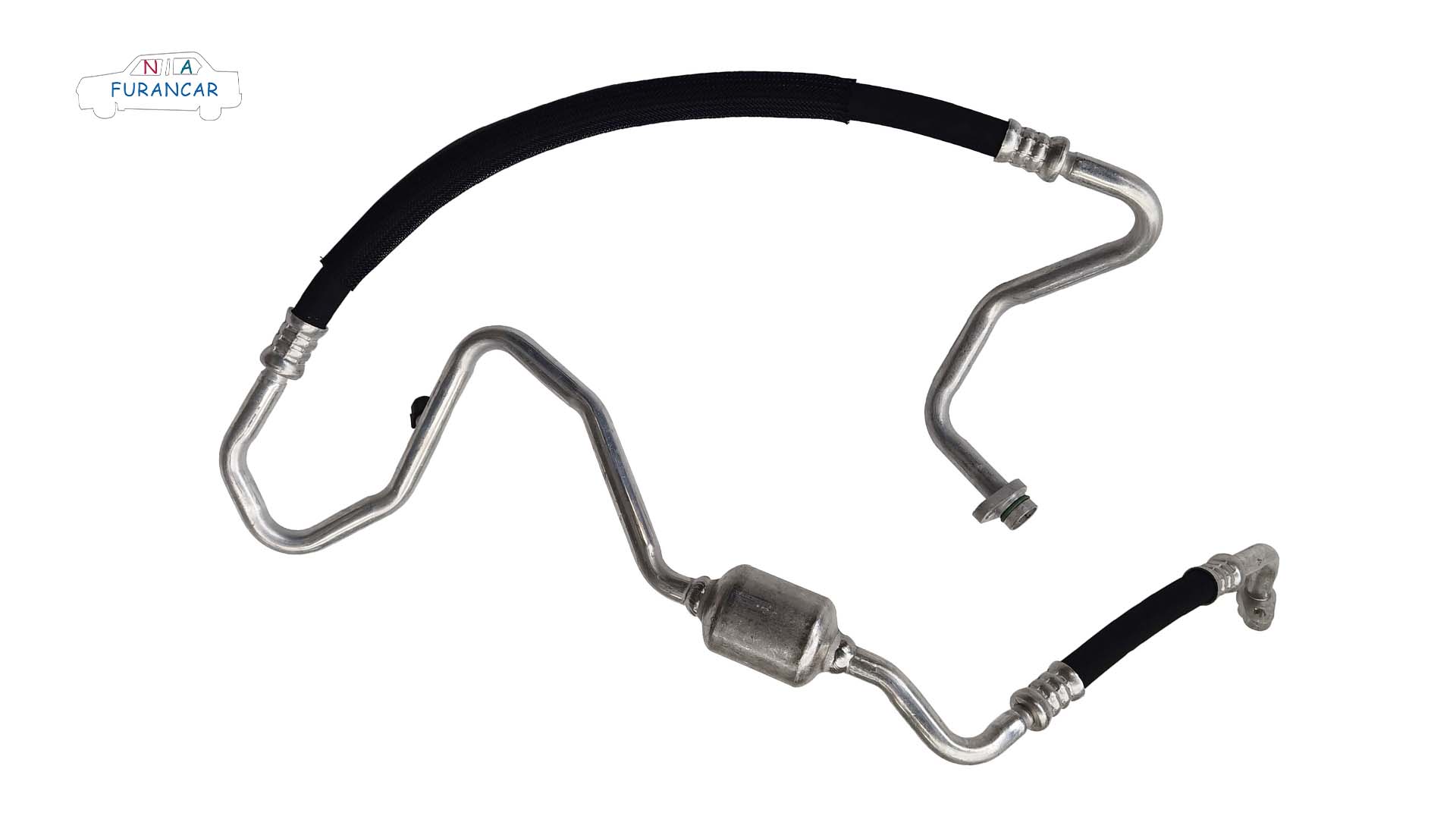
High- and low-pressure hoses and assemblies for vehicle steering systems

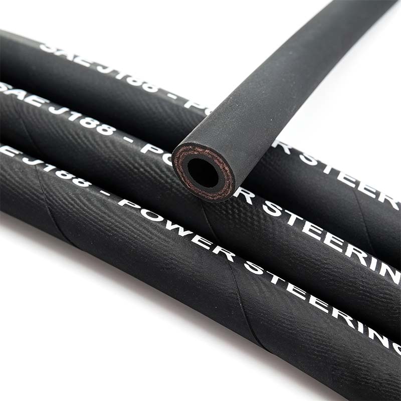
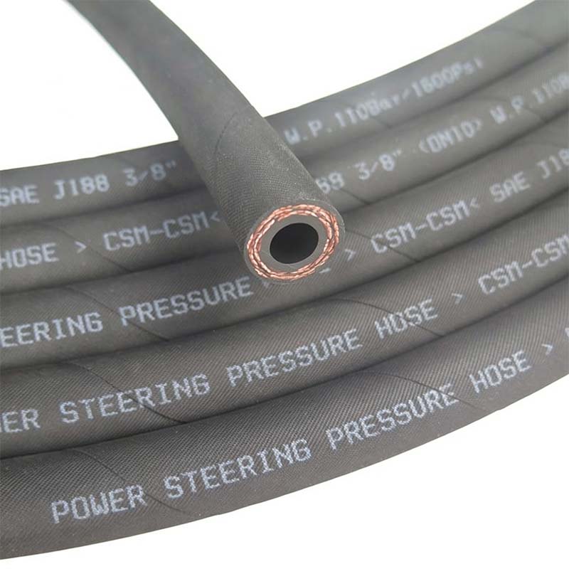
SAE J188 High-Capacity Intumescent Power Steering Hose


Application: For vehicles equipped with power steering systems, used to transmit pressure within the power steering unit.

Operating temperature: -40°C to 121°C, with a peak temperature of up to 135°C.

Standard inner diameter: 3/8”. The primary material is CSM, which offers excellent resistance to ozone, ageing, chemical corrosion, high and low temperatures, oil, abrasion, and electrical insulation.

Power Steering Hose


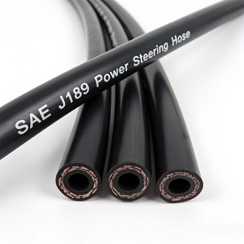
SAE J189 Low-Pressure Power Steering Return Hose

Application: For vehicles equipped with power steering systems; used to transmit pressure within the power steering unit.

Operating temperature: -40°C to 121°C, with a maximum instantaneous temperature of 135°C.

Common inner diameter: 3/8”.

Single-layer polyester filament braiding.

Power Steering Hose

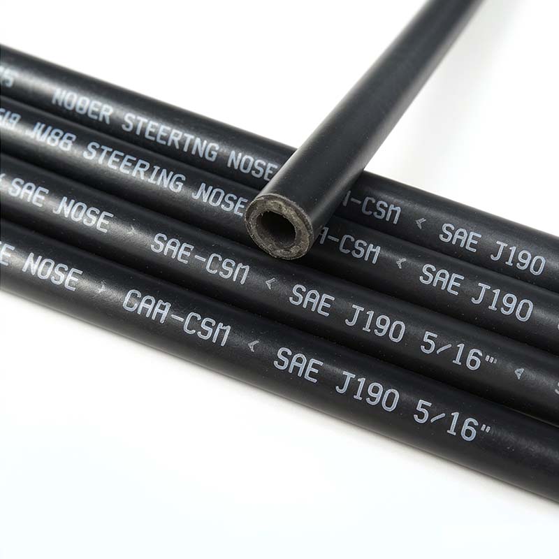
SAE J190 steel-braided power steering hose

Operating temperature: -40°C to 120°C.

Inner layer: NBR

Reinforcement: single or double layer of copper-plated steel braiding.

Outer layer: CR

Common inner diameters: 5/16”, 3/8”, 1/2”, 5/8”.

Typically used with crimp fittings.

Power Steering Hose

Steel-braided high-temperature power steering hose

Operating temperature: -40°C to 150°C.

Reinforcement layer: Two layers of polyester filament braiding. The main material is ACM, which offers excellent heat resistance, ageing resistance, oil resistance, ozone resistance and UV resistance. Its mechanical and processing properties are superior to those of fluorocarbon rubber and silicone rubber. Its heat resistance, ageing resistance and oil resistance are superior to those of nitrile rubber.

Power Steering Hose


How a car’s steering system works, common faults and solutions

I.How it works

Core function: to convert the rotation of the steering wheel into wheel movement, thereby steering the vehicle.


1. Mechanical steering (non-power-assisted).

Steering wheel → steering column → steering gear (rack and pinion/recirculating ball) → steering linkage → steering knuckle → wheel deflection; driven entirely by human effort.


2. Hydraulic power steering (HPS).

The mechanical structure is supplemented by a hydraulic pump, hydraulic hoses and a power steering cylinder. The engine drives the hydraulic pump to generate pressure, which assists the steering mechanism, making steering lighter.


3. Electric Power Steering (EPS).

Power assistance is provided directly by an electric motor, a torque sensor and a controller. It offers quick response, improved fuel economy and a simple design, and is currently the mainstream technology.

II. Common faults and solutions


1. Heavy steering; steering requires considerable effort.

Possible causes:

(1) Tyres are under-inflated.

(2) Hydraulic power steering system is low on fluid, has a leak, or the power steering pump is worn.

(3) Fault in the electric power steering motor or sensor.

(4) The ball joint on the steering tie rod or the plain bearing is seized.


Solution:

(1) Inflate the tyres to the recommended pressure.

(2) Check the power steering fluid; top up or replace it, and repair any leaks.

(3) Use a diagnostic scanner to read the EPS fault codes, and repair the sensors or motor.

(4) Lubricate or replace the ball joints and bearings.


2. Steering wheel pull (vehicle pulls to the left or right when driving in a straight line).

Possible causes:

(1) Uneven tyre pressure between the left and right tyres.

(2) Incorrect wheel alignment.

(3) Brake calipers sticking, causing uneven braking force between the left and right sides.

(4) Uneven lengths of the steering tie rods.


Solutions:

(1) Ensure all tyres are at the correct pressure.

(2) Have a four-wheel alignment carried out.

(3) Check the braking system.

(4) Adjust the steering linkage.


3. Steering noise (clunking or squeaking when turning the wheel).

Possible causes:

(1) Ageing of the steering ball joints or lower control arm rubber bushings.

(2) Wear on the plain bearings or top bushings.

(3) Stiff steering column universal joint.

(4) Noise caused by low fluid level in the power steering pump.


Solutions:

(1) Replace the ball joints and rubber bushings.

(2) Replace the shock absorber top bushings or plain bearings.

(3) Lubricate or replace the universal joints.

(4) Top up or replace the power steering fluid.

4. Steering wheel vibration and instability at high speeds.

Possible causes:

(1) Incorrect tyre balancing.

(2) Excessive play in the steering system.

(3) Warped wheel rims or bulging tyres.


Solutions:

(1) Have the tyres balanced.

(2) Check and tighten all components of the steering mechanism.

(3) Replace warped wheel rims or bulging tyres.


5. The steering lacks power and feels alternately light and heavy.

Possible causes:

(1) Blown EPS fuse or wiring fault.

(2) Power steering pump belt slipping or broken (hydraulic system).

(3) Power steering fluid too dirty or clogged.


Solutions:

(1) Check the fuse and wiring harness; repair the EPS module.

(2) Adjust or replace the belt.

(3) Replace the power steering fluid and flush the system.


6. The steering wheel is difficult to centre or does not return to its original position automatically.

Possible causes:

(1) Incorrect rearward or inward camber of the kingpins during wheel alignment.

(2) Sticking in the steering mechanism.

(3) Power steering system fault.


Remedies:
Perform wheel alignment, lubricate or replace steering components, and service the power steering system.

III. Recommendations for Routine Maintenance


1. Avoid turning the steering wheel fully to either side whilst stationary to reduce the load on the power steering system.

2. For vehicles with hydraulic power steering, change the power steering fluid regularly.

3. Have any unusual noises, pulling to one side or heavy steering checked as soon as possible to prevent minor faults from escalating.

4. Have a four-wheel alignment carried out promptly following an accident or any impact to the chassis.


Industry News | China’s automotive supply chain is shifting from supplying overseas markets to diversifying its presence

The EU’s stringent carbon emission regulations are driving the acceleration of electrification, yet Europe faces a severe shortage of domestic production capacity for batteries, electric drive systems and smart components, coupled with slow technological advancement and a reliance on external supplies. In 2024, China’s exports of automotive components totalled US$93.43 billion, with Europe representing the core growth market.


Nafurancar


I.Why accelerate now?

From ‘export products’ to ‘local roots’—the EU’s high tariffs (up to 45.3%), local content requirements (70% local production for non-battery components in electric vehicles), and the New Battery Act (covering carbon footprint, traceability and recycling) have effectively brought an end to the old model of ‘Made in China → Exported to Europe’, with local manufacturing now becoming a prerequisite for market access.


Maturity of China’s Supply Chain + Cost Advantage China possesses the world’s most comprehensive new energy vehicle supply chain, with manufacturing costs 20–30% lower than in Europe. Furthermore, it has established a technological lead in areas such as battery energy density, autonomous driving algorithms and sensors, which aligns with European carmakers’ core objectives of reducing costs and accelerating their transition.


II. From Supporting Roles to Diverse Penetration


  • Traditional supply chain exports

From the export of complete vehicles to the subsequent export of components, serving the European factories of Chinese car manufacturers (such as BYD and NIO). This model is characterised by passive supply, low value-added and a focus on trade. In the early stages, small and medium-sized component manufacturers exported items such as wheel rims, interior fittings and standard parts.


  • Establishing production capacity

Establishing factories in Europe, recruiting locally and serving local car manufacturers, thereby entering the supply chains of major players such as BMW, Mercedes-Benz, Audi, Volkswagen and Stellantis, and transitioning from a ‘Chinese supplier’ to a ‘local European Tier 1 supplier’.


Using Central and Eastern Europe (Hungary, Slovakia and Poland) as a bridgehead (due to low costs, favourable policies and proximity to Western Europe), whilst establishing R&D centres in Western Europe (Germany and Spain).


  • Technology transfer

Technology licensing + joint ventures + solution provision: earn technology fees and long-term royalties without building factories, and secure a position at the high end of the value chain.


  • Ecological permeation


With a fully integrated presence spanning R&D, testing, after-sales and local partnerships, we have evolved from a ‘parts supplier’ to a ‘technology partner’, forging close ties with European car manufacturers as they undergo transformation.


BYD’s European headquarters in Hungary (comprising sales, after-sales, R&D and testing) collaborates on research with local universities.


III. Key Challenges


  • Compliance barriers


EU REACH, PFAS restrictions and the Battery Regulation: with extremely stringent requirements regarding chemical traceability, carbon footprints and recycling systems, compliance costs for small and medium-sized suppliers are soaring, and they risk being forced out of the market.

Data compliance: Localised storage of autonomous/intelligent driving data and strict privacy protection; algorithms exported overseas must comply with EU regulations.


  • Cost and operational barriers


The cost of setting up a factory in Europe is two to three times that in China; labour costs are high, and unit production costs rise by 15–20 per cent, which must be offset through automation and lean manufacturing.

Strong trade unions and strict employment regulations: redundancies are difficult to implement, benefits are generous, and cross-cultural management presents significant challenges.


Domestic giants (Bosch, Continental and ZF) continue to dominate the high-end chassis and traditional powertrain components markets, drawing on a century of technical expertise.


Japanese and South Korean companies (Samsung SDI and LG Energy Solution) have a clear first-mover advantage, and competition in the battery sector is fierce.

Is your car’s air conditioning pipe leaking? Find out what causes this problem

Car air conditioning, an indispensable ‘must-have’ for driving in the sweltering summer heat, provides us with a comfortable environment whilst on the road.

If the compressor is the heart of the air-conditioning system, then the vehicle’s air-conditioning piping is its circulatory system, connecting the various air-conditioning components scattered throughout the vehicle to form a complete and efficiently functioning air-conditioning system.


Car air conditioning pipework typically consists of aluminium pipes, flexible hoses and other fittings.


Unlike other car components, air conditioning pipes do not need to be replaced very often, which means they are easily overlooked; as a result, some car owners fail to notice leaks in the pipework in good time.

Generally speaking, there are typically two causes of leaks in air conditioning pipes: 

  •  A blockage in the air conditioning system’s circuit, leading to prolonged high-temperature and high-pressure conditions between the compressor and the condenser, causing the PA layer on the inner wall of the rubber pipe to age and crack.  
  •  During the crimping of the aluminium sleeve, if the pipe is not positioned correctly, gas can escape from the top of the crimped area into the braided layer, penetrating the rubber layer and causing a general leak. This phenomenon is also known as a gas leak.

Although air conditioning hoses do not need to be replaced very often, over time they can accumulate dirt and grime that is difficult to clean out; it is therefore advisable to fit new ones. When replacing air conditioning hoses, be sure to choose products of guaranteed quality to avoid system faults caused by substandard hoses.

Performance requirements for hoses used in turbocharging systems

Turbocharging is a technology that uses the exhaust gases produced by an internal combustion engine to drive an air compressor. The primary function of turbocharging in cars is to increase the volume of air entering the engine, thereby boosting engine power and torque and making the vehicle more responsive. However, following turbocharging, both the pressure and temperature within the engine rise significantly; consequently, advancements in materials are also crucial when implementing turbocharging technology in engines.

High-temperature resistance

The gas in a turbocharger generates high temperatures due to compression and intense friction; even after cooling, the gas temperature generally exceeds 100 °C. Consequently, the materials used for hoses in turbocharger systems must be capable of withstanding high temperatures. Ordinary natural rubber, styrene-butadiene rubber (SBR) and polybutadiene rubber (BR) are unable to meet the requirements for use under high-temperature conditions; therefore, specialised high-temperature-resistant rubber materials must be employed. As turbocharger pressures continue to rise, the temperature of the gas passing through the hoses also increases. If the pressure reaches 3.5×10⁵ Pa, the temperature of the gas passing through the hoses can exceed 250 °C, and there are very few types of rubber capable of withstanding such high temperatures.


Oil Resistance

The gas passing through the hoses in a turbocharging system is generally contaminated with oil vapour; therefore, the hoses must possess a certain degree of oil resistance, particularly resistance to high-temperature oil vapour. Some rubbers with good high-temperature resistance (such as silicone rubber) have poor oil resistance, so an inner lining must be added to the inner wall of the silicone rubber hose to prevent corrosion from the oil vapour.

Strength

Turbocharging systems are not only subject to high temperatures but also to a certain degree of pressure; in particular, the pressure on the high-temperature sections of the piping is relatively high. Although reinforced hoses are generally used in turbocharging systems (with the reinforced layer constituting the primary pressure-bearing component), the rubber itself must also possess a certain degree of strength to enhance the overall strength of the hose. Furthermore, to meet the requirements of the manufacturing process and assembly, the rubber must also exhibit high tensile strength and tear strength.


Compression set

Generally, turbocharger hoses are connected to metal pipes using clamps to form a piping system. At high temperatures, the rubber must possess good resistance to deformation; otherwise, excessive compression set may cause the clamps to loosen and the hose to detach, leading to a safety incident.


Cold resistance

Although the hoses operate in a high-temperature environment once the engine has started, they are exposed to cold air once the engine is switched off. When the engine is started in cold conditions during winter in cold regions, the rubber hoses vibrate at low temperatures. If the rubber has poor low-temperature resistance, the hoses may become hard and brittle, leading to problems such as tearing, detachment and loss of vibration-damping capability.

Adhesion Strength

The rubber layer of a hose must maintain good adhesion to the reinforcement layer and the inner lining under harsh conditions such as cold, heat, and exposure to oil and gas, and must possess sufficient adhesion strength to ensure that delamination does not occur. Adhesion strength is dependent on the properties of the rubber itself and the rubber formulation, and is also closely related to the impregnation and pre-treatment of the reinforcement layer, the choice of adhesive, and the bonding process; therefore, all these factors must be thoroughly considered.


Hardness

The rubber should have a suitable hardness. If the hardness is too high, the hose will be too rigid to provide effective vibration damping, and will be difficult to fit and prone to coming loose; if the hardness is too low, sufficient strength cannot be guaranteed.

The Evolution of Automotive Turbocharger Hoses

Have you noticed that some vehicles on the road have a 'T' following the engine displacement figure in their model designation? This actually indicates that the vehicle's engine is fitted with a turbocharger. This device increases engine output power during high-speed driving whilst offering relative fuel efficiency.

The intake and exhaust intercooling system for automotive engines equipped with turbochargers typically comprises an air filter, turbocharger, intercooler, and connecting ductwork. The air delivery ducts must employ rubber hoses connected to steel pipes, or rubber hoses connected to blow-moulded pipes, or directly to corrugated blow-moulded pipes. The excellent flexibility and vibration-damping properties of rubber or corrugated blow-moulded pipes facilitate duct layout and assembly while significantly enhancing the air delivery system's capacity to absorb vibrations. Fresh air, after filtration through the air cleaner and pressurisation by the turbocharger, undergoes significant temperature rise during compression. Typically reaching 150°C to 200°C, gas temperatures in high-boost-ratio engines may exceed 200°C, even surpassing 275°C. Following cooling through the intercooler, the gas medium temperature drops below 60°C. This increases the density of the fresh air, enabling the engine to draw in greater volumes of air and inject more fuel. This promotes more complete combustion, thereby reducing fuel consumption and emissions while enhancing engine power output.


Turbocharger hoses, serving as the conduit between the engine and turbocharger, must withstand the swelling and ageing caused by high-temperature oil vapour during both the intercooler intake and exhaust processes, while maintaining flexibility at low temperatures. Given that turbochargers frequently operate under high-speed, high-temperature conditions—with exhaust turbine temperatures reaching approximately 600°C and rotor speeds of 8000–11000 rpm—all layers (inner, reinforcement, and outer) must exhibit resistance to high-temperature ageing. Consequently, inner layers typically employ ACM, VMQ, FKM, AEM, or EPDM compounds, while outer layers utilise ACM, VMQ, FKM, AEM, ABS (GDM), or similar materials. The reinforcement layer incorporates polyester or aromatic polyamide materials. These rubber compounds, capable of withstanding demanding operating conditions, are costly and relatively challenging to process. Consequently, developing an appropriate formulation system to achieve the desired performance while reducing costs to some extent represents a key challenge for turbocharger hose manufacturers and developers.

THERMAX N990 medium-particle pyrolytic carbon black is produced through the thermal cracking of natural gas. This pyrolysis process endows the carbon black with distinctive characteristics of large particle size and low structure. THERMAX N990 finds widespread application due to its ability to impart heat resistance, oil resistance, chemical resistance, and excellent dynamic properties to products. Its large particle size and low structure confer high fillability. Characteristics such as low compression set, high rebound elasticity, and low hysteresis enable the compound to retain the inherent elastomeric properties of rubber. As a non-reinforcing carbon black, the use of THERMAX pyrolytic carbon black in compounds is frequently employed to achieve cost reduction and obtain specific physical properties.


The use of THERMAX N990 in rubber compounds such as FKM and ACM/AEM demonstrates a superior overall balance of processing and product performance compared to any other carbon black variety. These favourable properties remain stable across varying filler levels and hardness requirements, outperforming other carbon blacks in product applications. THERMAX N990 serves as a cost-effective filler in FKM, ACM/AEM and similar rubber applications, particularly under high-filling conditions. High filling reduces polymer content in the compound, thereby lowering costs. Simultaneously, the inclusion of THERMAX N990 enhances the compound's resistance to oil and gas ageing, as well as high-temperature ageing. It also facilitates easier mixing and extrusion processes. It effectively addresses adhesion issues between inner/outer rubber layers and reinforcement layers. During high-pulse gas vibrations within the hose, it maintains excellent dynamic performance, thereby ensuring the longevity of the entire turbocharger system assembly.


THERMAX N990 Carbon Black ensures sustained power for your vehicle during high-speed driving.

The new debuts at the Paris Motor Show, priced from €34,200


Audi will unveil the facelifted A6 (available as a saloon and estate) at the Paris Motor Show this October, alongside the all-new high-performance RS6 variant. The updated models feature more fuel-efficient engines, retuned suspension systems, newly developed safety equipment, and the latest generation MMI multimedia interface.


  The signature Audi grille receives subtle refinement, while enlarged side air intakes lend the front end a more assertive and dynamic stance. The redesigned fog lights reflect contemporary styling cues. Customers may opt for xenon headlights with LED daytime running lights, with higher trims offering adaptive headlight technology that automatically adjusts illumination angles during cornering. Additionally, the optional SmartBeam high-beam assist system from Gentex is available. This system autonomously evaluates surrounding traffic conditions to switch between high and low beams, ensuring optimal illumination. By eliminating the need for manual high-beam switching, drivers can maintain greater focus on the road ahead.


  The new Audi A6 measures 4.93 metres in length, 1.86 metres in width and 1.46 metres in height, with only minor alterations to the body dimensions following revisions to the front and rear bumpers. Subtle refinements have been made to the side skirts, featuring a diffuser-like mesh between the twin exhaust pipes flanking the rear. The boot lid has been completely redesigned, with its opening transformed from a trapezoidal to a rectangular shape. The newly designed LED tail lights are more elongated, creating an even more dynamic atmosphere than the A5. Audi offers five body colours for the new A6.


  Interior modifications are more restrained than exterior changes, featuring subtle dashboard refinements and additional chrome accents. Valcona leather seats are available as optional equipment. The performance-focused S-line variant features 18-inch alloy wheels and a 30mm reduction in minimum ground clearance to lower the centre of gravity. All models benefit from Audi’s newly tuned suspension system for the A6.


  The most significant changes to the Audi A6 undoubtedly lie in its new powertrain. Engine engineers have reduced fuel consumption without compromising power, achieving an average fuel efficiency improvement of up to 15% across the entire range. The adoption of a new electronically controlled hydraulic power steering system has enhanced aerodynamic performance, while the addition of variable valve lift technology to the engine and an improved intake camshaft variable valve timing system further optimise torque delivery.


  The entry-level petrol engine for the new Audi A6 remains the 2.0-litre inline four-cylinder TFSI turbocharged unit, delivering a peak output of 170 hp. The top-of-the-range specification features a 4.2-litre V8 FSI producing 350 hp. Additionally available are a 2.8-litre V6 FSI delivering 190 hp and 220 hp respectively, alongside a newly developed 3.0-litre V6 TFSI turbocharged direct injection engine producing 290 hp. The new engines come standard with Tiptronic automatic transmission and Quattro permanent all-wheel drive. Acceleration from 0 to 100 km/h takes just 5.9 seconds, with electronic speed limitation at 250 km/h. Combined fuel consumption is a modest 9.5 litres per 100 kilometres.


The entry-level diesel engine is a 2.0-litre TDI producing 136 hp, alongside a differently tuned 170 hp variant. Next comes the more potent 2.7-litre V6, delivering a maximum output of 190 hp and 380 Nm. The top-of-the-range specification features a 3.0-litre V6 TDI, achieving peak figures of 240 hp and 450 Nm. Notably, the 2.0-litre TDI achieves a combined fuel consumption of just 5.3 litres per 100 kilometres – a commendable figure in today's climate of high fuel prices. Engines delivering 190 hp or more may be equipped with Audi's Quattro permanent all-wheel drive system.

  Following its global debut at the Paris Motor Show in October, the new Audi A6 commenced sales across European markets. The entry-level variant, equipped with the 2.0-litre TFSI engine, carries an estimated price tag of €34,200 (approximately RMB 350,000). It is anticipated that the domestic A6L will undergo a corresponding facelift, though the timing remains unconfirmed.

Turbocharger Oil Feed Pipe Manufacturing Process Explained

Modern turbocharged engines rely heavily on stable lubrication and oil circulation to maintain performance and durability. One small but critical component in this system is the Turbocharger Oil Feed Pipe. Although it may appear simple, the manufacturing quality of this pipe directly affects turbocharger lifespan, oil flow stability, sealing performance, and overall engine reliability.

For European aftermarket customers and OEM buyers, understanding how a Turbocharger Oil Feed Pipe is manufactured helps evaluate product quality, material standards, and supplier capability.

This article explains the complete Turbocharger Oil Feed Pipe manufacturing process, including raw materials, bending, welding, testing, and quality control procedures.


What Is a Turbocharger Oil Feed Pipe?


A Turbocharger Oil Feed Pipe is responsible for delivering pressurized engine oil from the engine block to the turbocharger bearing housing. The oil lubricates and cools the turbocharger shaft and bearings during high-speed operation.


Without proper oil supply:

  • Turbocharger bearings may overheat
  • Shaft wear may increase
  • Turbo efficiency may decrease
  • Oil leakage or turbo failure may occur


The Turbocharger Oil Feed Pipe must therefore withstand:

  • High temperature
  • High pressure
  • Continuous vibration
  • Long-term oil exposure

In European vehicles such as BMW, Mercedes-Benz, Volkswagen, Renault, and Volvo, the oil feed pipe design often requires precise bending angles and accurate OE fitment.


Raw Materials Used in Turbocharger Oil Feed Pipes


The durability of a Turbocharger Oil Feed Pipe begins with material selection.


Carbon Steel Pipes

Carbon steel is widely used in aftermarket turbocharger oil pipes because of its:

  • Good strength
  • Cost efficiency
  • Stable production performance

After bending and forming, carbon steel pipes usually receive surface treatment such as galvanizing or anti-corrosion coating.

However, poor drying after chemical treatment may sometimes cause internal oxidation or slight rust inside the pipe.


Stainless Steel Pipes

Stainless steel Turbocharger Oil Feed Pipes provide:

  • Better corrosion resistance
  • Longer service life
  • Improved appearance
  • Higher temperature resistance

Many European aftermarket customers now prefer stainless steel solutions for demanding applications or harsh environments.

Although stainless steel pipes have higher production costs, they significantly reduce the risk of internal corrosion.


Rubber Hose and Sealing Materials

Some turbo oil pipe assemblies include flexible hose sections and sealing components.

Common sealing materials include:

  • NBR (Nitrile Rubber)
  • FKM / Viton® for higher temperature resistance

Material selection depends on:

  • Oil temperature
  • Pressure requirements
  • Vehicle application
  • OE specifications

Turbocharger Oil Feed Pipe Manufacturing Process

The Turbocharger Oil Feed Pipe manufacturing process involves multiple precision production steps.


1. Tube Cutting

The process begins with raw steel tubing.

The tubes are cut according to OE dimensions using automatic cutting machines to ensure:

  • Accurate length
  • Clean edges
  • Stable production consistency

Cutting accuracy is important because even small deviations may affect installation and oil sealing.


2. CNC Tube Bending

After cutting, the pipe enters the CNC bending process.

Turbocharger Oil Feed Pipes often have complex shapes because they must fit inside crowded engine compartments while avoiding:

  • Engine vibration interference
  • Heat sources
  • Other engine components

Precise bending ensures:

  • Correct oil flow path
  • Proper installation angle
  • OE-level fitment

Advanced CNC bending machines help maintain dimensional consistency during mass production.


3. Welding and Joint Assembly

Many Turbocharger Oil Feed Pipes require:

  • End fittings
  • Connectors
  • Brackets
  • Banjo joints

These components are welded or brazed onto the pipe assembly.

Welding quality is extremely important because poor welding may lead to:

  • Oil leakage
  • Cracks
  • Pressure failure

Professional manufacturers usually control:

  • Welding temperature
  • Joint penetration
  • Surface cleanliness
  • Welding consistency


4. Cleaning and Internal Treatment

After welding, internal cleaning becomes critical.

Metal debris, welding residue, or chemical contamination inside the pipe may damage the turbocharger.

The cleaning process may include:

  • High-pressure flushing
  • Air cleaning
  • Ultrasonic cleaning
  • Internal drying

Some manufacturers also apply anti-rust oil protection inside the pipe to reduce oxidation risk during storage and transportation.

This step is especially important for carbon steel Turbocharger Oil Feed Pipes.


5. Surface Treatment

To improve corrosion resistance and appearance, the pipe surface usually receives treatment such as:

  • Zinc plating
  • Electroplating
  • Galvanizing
  • Anti-corrosion coating

Good surface finishing improves:

  • Rust resistance
  • Product appearance
  • Long-term durability

European aftermarket customers often pay close attention to surface consistency and coating quality.


Pressure Testing and Quality Inspection

Reliable Turbocharger Oil Feed Pipe manufacturers perform strict quality testing before shipment.

Leakage Testing

Each pipe assembly may undergo air or oil leakage testing to ensure:

  • No pinholes
  • No sealing failure
  • Stable pressure resistance

Leakage testing is one of the most important quality control procedures.


Burst Pressure Testing

Burst testing verifies the pipe’s maximum pressure capability.

High-quality Turbocharger Oil Feed Pipes must withstand pressures far above actual operating conditions to ensure safety and durability.

Dimensional Inspection

Manufacturers also check:

  • Pipe angle
  • Connector position
  • Thread accuracy
  • Installation dimensions

Optical measuring systems and custom fixtures are often used for OE verification.

Common Problems in Turbocharger Oil Feed Pipes

Understanding common failure modes helps improve product reliability.

Inner Corrosion

Internal corrosion is one of the most common aftermarket concerns.

Possible causes include:

  • Residual moisture after galvanizing
  • Poor drying process
  • Long-term storage conditions

Complex pipe bending structures sometimes make internal drying more difficult.

To reduce this risk, manufacturers may:

  • Improve drying procedures
  • Apply anti-rust oil
  • Use stainless steel materials

Oil Leakage

Oil leakage may result from:

  • Poor sealing
  • Improper welding
  • Incorrect assembly
  • Low-quality fittings

Even minor leakage may eventually affect turbocharger performance.

Oil Flow Restriction

If the inner diameter becomes restricted, oil supply to the turbocharger may decrease.

Possible causes include:

  • Internal contamination
  • Pipe deformation
  • Incorrect bending
  • Excessive welding residue

Stable oil flow is essential for turbocharger cooling and lubrication.

How Manufacturers Improve Turbocharger Oil Pipe Reliability

Professional Turbocharger Oil Feed Pipe manufacturers continuously improve production processes.

Common improvement measures include:

  • Better internal cleaning systems
  • Improved anti-rust protection
  • Higher quality welding control
  • Upgraded surface finishing
  • More accurate CNC bending
  • Enhanced pressure testing standards

For European aftermarket customers, these improvements help reduce:

  • Warranty claims
  • Oil leakage issues
  • Installation problems
  • Long-term durability risks

How to Choose a Reliable Turbocharger Oil Pipe Manufacturer

When selecting a Turbocharger Oil Feed Pipe supplier, buyers should evaluate more than price alone.

Important factors include:

OE Development Capability

A reliable supplier should support:

  • OE sample development
  • Drawing-based production
  • Vehicle application matching
  • Small batch customization

Quality Control System

Professional manufacturers should provide:

  • Leakage testing
  • Burst pressure testing
  • Dimensional inspection
  • Material verification

IATF 16949 certification is also an important advantage for automotive suppliers.

European Aftermarket Experience

Suppliers familiar with European vehicles generally understand:

  • OE fitment requirements
  • Surface quality expectations
  • Packaging standards
  • Long-term aftermarket durability

Conclusion

The Turbocharger Oil Feed Pipe may be a relatively small component, but its manufacturing quality plays a major role in turbocharger reliability and engine performance.

From raw material selection and CNC bending to welding, cleaning, and pressure testing, every production step affects the final product quality.

For aftermarket buyers and OEM customers, choosing a professional Turbocharger Oil Feed Pipe manufacturer with strong quality control and technical capability is essential for long-term reliability.

If you are looking for reliable aftermarket Turbocharger Oil Feed Pipe solutions for European vehicles, working with an experienced manufacturer can help ensure stable quality, OE fitment, and long-term cooperation.
Use and Maintenance of Automotive Air Conditioning Systems

Summer is just around the corner. As we all know, a good car air-conditioning system can cool the car down quickly and ensure a comfortable drive, but we often don’t really know how to use the air-con properly or how to maintain and look after the system. We often find ourselves in this situation: when we switch on the car’s air conditioning in sweltering, blazing heat, we discover that the system is malfunctioning, which can be quite a worry. To address these issues, we’ll provide a detailed guide on the correct use of your car’s air conditioning system and the key points to bear in mind during its maintenance and upkeep.


Turning on a car’s air conditioning system may seem like a straightforward task, but in reality, it is easy to overlook the correct methods and precautions. Whilst we do not need to fully understand how the entire system works or its complete structure, it is essential to know the correct way to use it and how to maintain it properly. Understanding these points not only improves the efficiency and durability of your car’s air conditioning but also ensures the system remains in good working order, as its condition directly affects our health.

AC Hose

Turn on the car air conditioning regularly


Firstly, the cool air blown out of the car’s vents passes through the blower fan, the evaporator in the air-conditioning system, the small reservoir in the heating system, and the air ducts. Over time, these systems accumulate significant amounts of dust and moisture; if not used or maintained properly, this can lead to mould growth and encourage the proliferation of bacteria, the harm to our health being self-evident.


When using the car’s air conditioning system for the first time after a change of season, you should open the car doors, switch to the external air circulation mode and set the fan to high. You should then step out of the vehicle, leave the system running for at least two minutes, switch it off, and clean the seats and carpets inside the car. This is done to expel as much bacteria and dirt as possible from the air conditioning system, which has been left unused for a long period, thereby preventing any adverse effects on the quality of the air inside the vehicle and reducing potential harm to the driver and passengers.


During other seasons when the air conditioning is not required for cooling, you should still switch it on at least once a month. Leave it running for just 30 seconds before switching it off. This ensures that the compressor and all the pipes remain well-lubricated, prevents leaks and the deterioration of hoses, and enhances the durability of the air conditioning system.


In direct sunlight, let the air heat up first before switching to cooling


When a car is left parked in direct sunlight, the temperature inside can reach 50°C or even higher. This makes getting into the car a real ordeal for the driver. Even with the air conditioning switched on, it is difficult to bring the temperature down quickly enough. At best, one might feel a slight coolness from the vents, whilst the seat and backrest remain unbearably hot.


In fact, before getting into the car, open all the windows or doors to let the hot air out. Switch on the fan and the fresh air mode (without turning on the cooling function just yet) to speed up air circulation and quickly dispel the heat from inside the car. Only then should you get in, close the windows and doors, and switch on the cooling function. Doing this will naturally improve the cooling performance and efficiency of the air conditioning.


Avoid leaving it switched on for long periods


Some motorists, for the sake of convenience, leave the air conditioning running continuously during the summer. However, when a vehicle is cold-started, neither the lubrication provided by the engine oil nor the operating temperature of the cylinders is at an optimal level. Under these conditions, the load on the engine and the resulting wear are the most severe of all operating conditions. Furthermore, running the air conditioning compressor and blower fan simultaneously increases the load on both the engine and the electrical system, causing unnecessary wear to the engine whilst also resulting in suboptimal cooling performance. Therefore, the air conditioning system should be switched off when starting the vehicle.


However, during the cooling process, car air conditioning systems accumulate a significant amount of moisture inside. If the engine is switched off immediately, this trapped moisture cannot be expelled quickly enough; over time, this leads to mould forming inside the air conditioning ducts, thereby fostering the growth of bacteria that are harmful to our health. If you notice a sour, musty odour whilst using the air conditioning, this is typically the result of prolonged improper use. To address this issue, three minutes before reaching your destination, switch off the cooling function and set the system to fresh air mode. This allows as much moisture as possible to be expelled from the system, thereby reducing the likelihood of mould growth inside the unit.

AC Pipe

The operating time should not be too long


Many drivers set their air conditioning to the lowest temperature and leave it on for long periods to combat the sweltering heat of summer. However, this is actually very detrimental to one’s health. Due to the significant temperature difference between the inside and outside of the vehicle, excessively low temperatures inside the car can easily cause passengers who have just stepped in from a hot environment to develop heat-related colds or flu-like symptoms. Furthermore, prolonged exposure to a cold air-conditioned environment increases the risk of developing ‘air-conditioning sickness’. For air conditioning systems with automatic climate control, we recommend setting the temperature between 22°C and 26°C.


Finally, it is crucial to note that many drivers often leave their cars parked in garages with the air conditioning running whilst they rest. This practice carries a high risk of carbon monoxide poisoning. In enclosed spaces, carbon monoxide from vehicle exhaust fumes accumulates and is drawn into the cabin through the air conditioning system’s air intake, causing carbon monoxide levels to rise. This can lead to poisoning and, in severe cases, even death. Therefore, when a vehicle is in a relatively enclosed environment, the air conditioning should be switched off and the engine turned off.


When using the high-pressure air condition hose in recirculation mode for extended periods whilst parked outdoors, the lack of air circulation causes the air inside the vehicle to become stale. Driving for long periods in such an environment can lead to dizziness and a foggy head, which may affect the health of both the driver and passengers. It is therefore not advisable to use the recirculation mode with the windows closed for long periods. During long journeys, you should switch to fresh air mode frequently and stop to rest at appropriate intervals to alleviate fatigue. Furthermore, in older vehicle models with poor heat dissipation, leaving the air conditioning running for an extended period after parking may cause the coolant temperature to rise excessively, which in severe cases could result in engine damage.

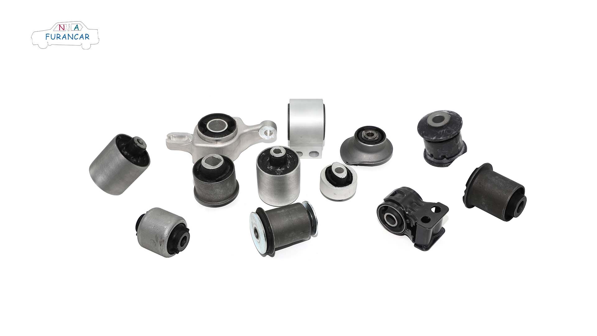
What are automotive bushings? What is their function?

If you hear a ‘creaking’ noise coming from the car’s chassis, accompanied by the steering wheel pulling to one side whilst driving, it could be a problem with the suspension bushings. Today, we’ll take a look at what you need to know about car bushings.


What is an automotive bushing?


In mechanical design, the connection of moving parts is a common requirement; however, relative motion between components can easily lead to friction and wear. To address this issue, flexible coupling solutions are widely adopted—not only do they effectively reduce wear, but they also make replacement more convenient and cost-effective should wear and damage occur later on. It is for this reason that industrial bushings have come into being. 


In the automotive sector, bushings are elastic, flexible connecting components installed at the joints of moving parts such as the chassis suspension system and control arms. They are typically made from elastic materials such as rubber or polyurethane (or a composite structure combining a metal skeleton with an elastic material), and their core function is to replace rigid connections, thereby resolving the issue of friction and wear caused by the relative movement of components. 


Put simply, they act as a ‘shock absorber and wear-resistant joint’ between chassis components.


What is the purpose of a bushing?


Chassis bushings play a crucial role in the construction of a vehicle’s chassis. Their primary function is to connect the chassis to the suspension system, preventing rigid connections, protecting metal components and absorbing shocks, thereby ensuring the vehicle’s stability and comfort whilst in motion. Chassis bushings must not only bear the vehicle’s weight and inertia but also cope with a variety of complex road conditions and driving scenarios. A high-performance chassis bushing can significantly enhance the vehicle’s ride quality, reduce tyre wear and suspension fatigue, and provide the driver with a more enjoyable driving experience. 


Chassis bushings can be categorised into various types based on different classification criteria: these include front and rear axle bushings, tie rod bushings, control arm bushings, subframe bushings, hydraulic and non-hydraulic bushings, as well as metal and nylon bushings, and open and closed bushings. Although the classifications vary, the functions they perform are similar.

Bushing

Points to note when replacing bushings


1. Selection of press-fit sleeves

When removing or pressing in components, select a sleeve of the appropriate size to ensure that the force is applied to the outer ring of the bushing, whilst other parts remain unloaded. Wear safety goggles and gloves when carrying out this work. The dimensional information provided in the Codic product manual can assist in selecting the correct sleeve. 


 2. Press-fit Force

To facilitate installation, remove any burrs from the inner bore prior to pressing and apply a small amount of lubricant (such as 4240 grease) to the inner bore and the initial section of the outer diameter. Ensure that the press-fit force is not too low; for bushings with an outer tube diameter of 40 mm, the press-fit force for metal outer tubes should generally exceed 6 kN, and for nylon outer tubes, it should exceed 20 kN, with values varying according to the diameter of the outer tube. If the pressing force is found to be too high or too low, check the condition of the inner bore and verify that the correct bushing has been selected.


3. Confirmation of Installation Position
During installation, ensure that the solid section is aligned with the horizontal direction of travel. If the product features an arrow, ensure that the arrow points in the horizontal direction of travel. Ensure that the pressing position is centred, with equal lengths protruding from both ends.

4. Stress Relief
Once installation is complete whilst the vehicle is raised off the ground, stress concentrations often develop in the chassis system. To resolve this, the vehicle must be lowered to the ground and the steering wheel centred. The fasteners should then be loosened to the specified torque, before being retightened to the standard torque to release the stress and allow the chassis to return to its original state. At this point, the vehicle is as though fitted with a brand-new pair of running shoes, ready to roam freely.